
The measurement of the current is a troublesome task for a multimeter. Especially, when a running circuit is checked for current, things get complicated. Clamp meters suppressed this trouble.
Clamp meters use different approaches for current measurement. The method used in clamp meters is safe and accurate. Hence, we get not only accurate measurements but also our safety is protected.
Now you may be wondering how a clam meter works.
The working of a clamp meter is simple and efficient. A simple clamp meter works on the principles of electromagnetic induction (for AC) and Hall’s effect (for DC). Once the current is induced in the clamp jaw, that induced current is fed to other circuitry for conditioning and then the measured current is displayed on the screen.
Here, in this article, we are going to learn everything about the working principles of clamp meters.
How Does a Clamp Meter Work?
In clamp meters, the jaw of the clamp meter detects the current through electromagnetic induction. Electromagnetic induction is a common phenomenon for motors and generators.
This mode of detection ensures the safety of users. Moreover, the current and clamp meter are electrically insulated and magnetically connected. It makes clamp meters protected from accidents.
Working Principles of a Clamp Meter
A simple clamp meter works on two principles: Electromagnetic induction and Hall’s effect. We are going to discuss each below:
1. Electromagnetic Induction
The change in a magnetic field produces (or induces) an opposing current in a nearby conductor. This phenomenon is called electromagnetic induction.
This change in magnetic field can occur by two methods:
- Change in Current
- Change in Position
In the case of the clamp meter, we use the change in current. This occurs automatically for AC as the polarity of current changes in AC.
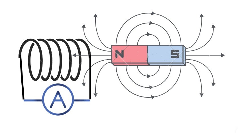
Hence, a change in the magnetic field due to alternating current induces current in the clamp meter’s jaw. The induced current is further fed to the signal conditioner circuit.
Strictly saying, this method only works for AC.
2. Hall’s effect
Current carrying conductor, when exposed to an electromagnetic field, the flow of current is affected. Positive and negative charges follow opposite to each other in the same semiconductor and create potential differences.
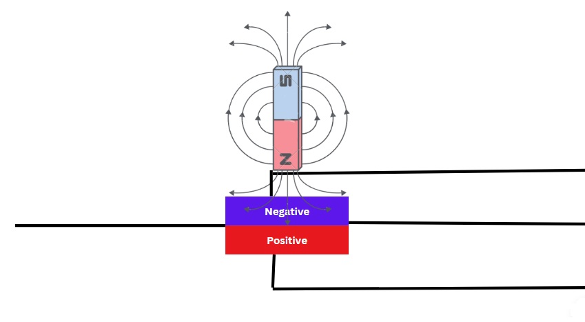
This potential difference is created according to the value of the current responsible for electromagnet production. The potential difference is sensed by the internal circuit for further processing.
It means if the current is more, the value of the electromagnetic field will be maximum hence the potential difference.
This phenomenon occurs in Hall’s sensors, which are used for detecting DC. The electromagnetic field will always be perpendicular to the conductor.
These two methods are used for detecting current. Further processing is discussed below.
Working Process of a Simple Clamp Meter
After detecting the current (AC or DC), the induced current is passed through different stages. Let’s discuss each stage briefly:
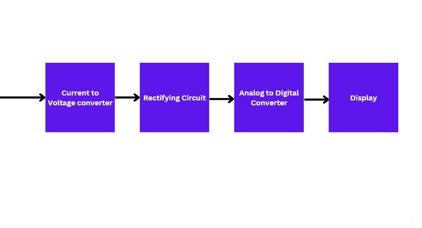
1. Current to Voltage Converter
This stage is responsible for the conversion of the current into voltage for further conditioning. The input of this stage is the induced current while its output is voltage.
The advantage of voltage over current is simple. As we are dealing with digital circuits in the next stages, processing voltage signals is easier than the current signal.
2. Rectifying Circuit
Our task is to get an accurate measurement from a clamp meter. The converted voltage may have some shift in polarity. This needs to be rectified. In this regard, rectifying the circuit changes the multiple polarity to a single one.
Hence, the input to this stage is an un-rectified voltage and the output is a rectified voltage.
The processing circuit of the analog clamp meter works till this stage. The rectified voltage is fed to a current-carrying coil placed in a magnetic field resulting in the rotation of the coil.
The coil is wounded around a rotor. The rotor has a needle on the dial. Upon movement, the corresponding reading is displayed.
3. Analog to Digital Converter
The input voltage is, as obvious, analog. We need to represent this voltage value in digits on display. Hence, an analog signal would not help us.
For this purpose, the voltage signal is changed to digital in this stage. The output of this stage is multiple-wired and more explanatory.
Be informed that this stage is installed only in digital clamp meters.
4. Display
The final refined signal is fed to the LCD of a clamp meter. The LCD is the output hardware of a clamp meter because it shows data to the user.
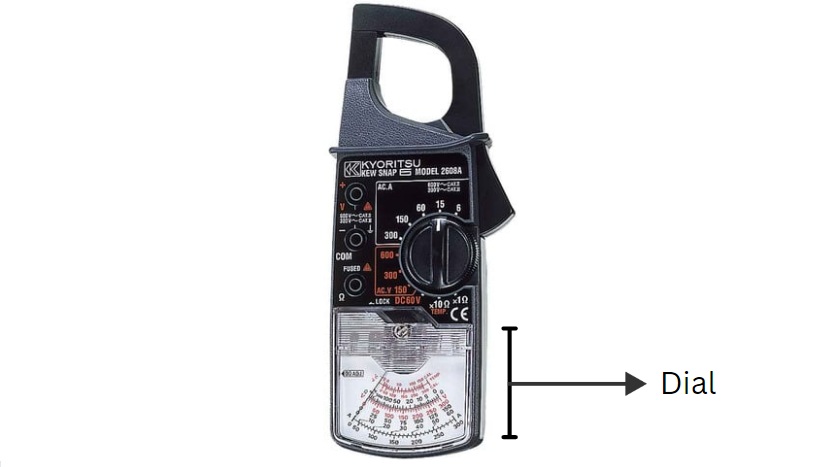
As we discussed earlier, the analog clamp meter does not have an LCD. In contrast, it has a dial with a different range of values. The result is shown through a needle on a corresponding value on the dial.
Modern Clamp Meters
Modern clamp meters are more advanced and up-to-date. Manufacturers installed many relevant functions in their design and the number of hardware get increased.
We will discuss a few common functions frequently seen in modern clamp meters below:
1. Number Measuring Parameters
According to the needs of users, approximately every clamp meter has the facility to measure differential temperature. The values are given in Centigrade and Fahrenheit.
Measuring Resistance and Capacitance are commonly found in modern clamp meters. They are measured in different units.
We can also measure Frequency through nowadays clamp meters.
2. Durability
Extra care has been given to the durability, toughness, and sustainability of a clamp meter. For this purpose, the internal circuitry is connected to the body through a special separation of plastic.
Additionally, extra casing helps to increase toughness and sustainability. We feel comfortable due to these installments in modern clamp meters.
3. Control Panel
The simple and old design of the clamp meter consists of a limited number of options. Generally, these clamp meters would have a single task, to find the AC.
Nowadays, clamp meters have many functions and different ranges. Hence, control panels were installed to give us more freedom in selecting and optimizing the reading.
Knobs, push buttons, or plugs are installed to give users a variety of options.
4. LCD Screen
Of course, the quality of LCD is a measuring factor. An advanced clamp meter is supplied with high-quality LCD to give us the maximum and accurate reading.
As we would be dealing with low and high currents, the display needs to be amenable to our requirements.
Hence, a good LCD promises a good clamp meter.
Conclusion
A clamp meter is a simple instrument with many sophisticated circuitry. This simple and accurate measurement technique made our tasks effortless.
These clamp meters work on the principles of electromagnetic induction (for AC) and Hall’s effect (for DC). Both detect current by using the electromagnetic field of current-carrying wire.
The induced current is passed through conditioning circuits. These circuits convert current into voltage, rectify the voltage, convert it to a digital signal, and then display it on the LCD.
However, modern clamp meters have more functions than the above. Hence, the circuitry of modern clamp meters hosts more hardware.
Although the internal circuit of the clamp meter gets more complicated, the aim is to provide users with more efficient functions.
Other useful posts: