
A clamp meter is an effective tool that allows us to measure current in a very advanced and safe way. After the successful introduction of a clamp meter, the need for the same instrument for resistance was felt for the ground.
For this purpose, the Ground Resistance Clamp was introduced which is a variant of a clamp meter. This clamp meter not only reduced work effort but also improved accuracy.
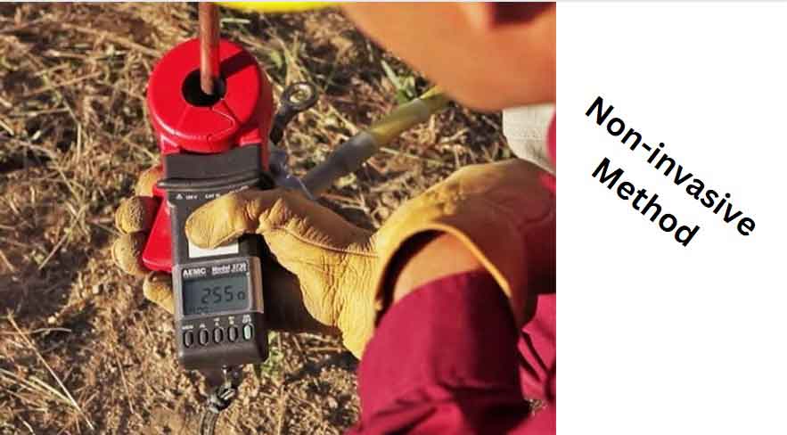
Just like a clamp meter, we open the jaw of a ground resistance clamp and place it around the ground wire (or a conductor). The corresponding value of resistance is shown on the LCD of the clamp meter. The value of resistance should be the lowest possible for a good ground. It means these clamp meters are sophisticated.
Let’s study more about the ground resistance clamp.
How to Measure Ground Resistance Through a Clamp Meter?
Through a clamp meter, we can easily measure ground resistance. The method is the same as that of measuring current. However, we must be careful about the orientation of our workplace to quell any danger.
The clamp meter is placed around ground or earth wire. The corresponding value of resistance will appear on the display of the clamp meter.
Measuring Ground Resistance
Calculating the value of ground resistance is as important as the wiring itself. By knowing the value, we can reckon the quantity of resistance faced by the short current.
Different safety forums strictly advise it. Let’s study the ground resistance before discussing the ground resistance clamp.
What is Ground Resistance?
Ground resistance is the resistance faced by the current dumping into the ground in the situation of short-circuiting (or short-wiring).
The value of ground resistance should be as low as possible. Due to its low value, the current will pose a little resistance to flow to earth than to shock someone.
The high value of ground resistance is dangerous. At least, the value of ground resistance must be higher than that of the human body. In this way, the lives could be saved.
Before moving further, let’s talk about important parameters relevant to this blog.
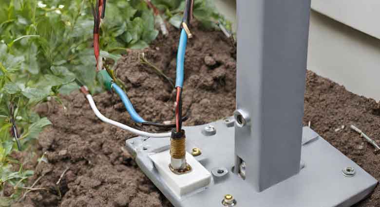
1. Grounding/Earthing
Grounding is the phenomenon through which a low resistance reference point is set for a circuit or wiring. We use it as a reference point to measure voltage, current, or resistance.
When it comes to safety, grounding plays a vital role. It is highly advised to monitor the value of resistance after a week.
The term earthing is used when that reference point is attached to earth in a specific manner. Copper in combination with carbon is a good method for earthing.
Skyscrapers, towers, transmission lines, and circuits are protected from lightning through earth wires.
2. Resistance
The opposition to the flow of current is called resistance. The value of resistance is measured in Ohms (Ω). It is the 3rd essential electrical parameter after current and voltage.
The more resistance reduces the flow of current. Ideally, the resistance value needed to be zero for the good flow of current.
Electrical current always follows the shortest path for its flow. We design grounding keeping the resistance as low as possible.
Area, length, material, and temperature affect the value of resistance. That’s why monitoring the value of ground resistance is always advised.
3. Clamp Meter
A clamp meter is an instrument that measures current without disturbing the circuit. It is an innovative method of measuring current.
Clamp meters not only provide safety in measuring but also give maximum accuracy.
We have discussed the clamp meter in a separate blog. The link is given below to learn more about clamp meters.
These were some important terms for our blog. Let’s learn about clamp meters used for measuring ground resistance.
Ground Resistance Clamp
The Ground resistance clamp is a modified clamp meter. This clamp meter measures resistance, not through probes, but through the clamp.
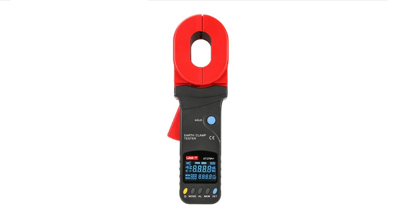
The clamp is a U-shaped conductor and a coil, that senses current through electromagnetic induction. This happens because a current-carrying wire generates an electromagnetic field.
We will be calling the current in the ground conductor as a source current. Let’s study the working of a ground resistance clamp…
1. Sensing Current
The generated electromagnetic field of a current-carrying wire induces a current in the clamp of the ground resistance clamp. This method is called mutual induction and is common in transformers.
The value of the induced current is proportional to the value of the source current. Hence, a little change in source current is duly observed.
2. Conversion
The induced current generates voltage. Again the value of the voltage depends on the source current. The change in source current is meticulously observed by the sophisticated assembly.
The reason behind the conversion is that voltage is easy to process in digital circuits. Voltage reduces the chances of heating the internal circuit.
3. Calculation
The internal circuitry of the ground resistance clamp calculates the value of resistance from the induced voltage. The integrated circuit with the combination of other circuit components performs the task.
The chances of error are less than the common method of measuring ground resistance. Regardless of material, temperature, area, or length; the value of ground resistance is calculated through the flowing current.
4. Displaying the Value
The value is then displayed on the LCD. The whole process takes a few seconds. We can observe that this phenomenon of calculating ground resistance clamps is smoother than the common method.
It would be astonishing if you did not get confused now about the difference between a clamp meter and a ground resistance clamp.
Let’s observe how these two are different.
Difference Between Clamp Meter and Ground Resistance Clamp
The difference between a clamp meter and a ground resistance clamp is very minute. The ground resistance clamp is the modified version of the clamp meter.

Let’s see their differences in the following table.
| S.No | Assessing | Clamp Meter | Ground Resistance Clamp |
| 1 | Purpose | Measuring Current | Measuring Resistance |
| 2 | Target | Measurement of Value | Monitoring |
| 3 | Uses | General | Specific |
| 4 | Measuring parameters | Versatile | Only Resistance |
| 5 | Checking | Wire | Ground conductor |
| 6 | Reason of usage | Measurement | Assessment |
These are the key differences between a clamp meter and a ground resistance clamp. Besides these, both are the same things.
Conclusion
A ground resistance clamp is a modified clamp meter. This type of clamp meter aims to measure only the resistance of the ground conductor.
The ground is a reference point for a circuit or wiring. If the reference point is Earth, we call it simply Earth instead of ground.
The conductor used for grounding is called the ground conductor. Copper is an ideal material for this purpose. The resistance to current flow through the ground conductor is called ground resistance.
Ground resistance clamp is a modified clamp meter that uses the same phenomenon of a clamp meter to measure resistance. The value is calculated through a non-invasive mean.
The induced current is converted to voltage after sensing the current through electromagnetic induction. This voltage is used for the measurement of resistance by the internal circuit. Hence, the value is then displayed on LCD.
Other useful blogs: